A Brief Descriptor
This portfolio aims to describe the many significant projects and experiences that I've completed throughout my life. Each project will be described in varying detail with respect to the project's complexity, and with respect to how much I have to say about it.
Hackathons (24hr Engineering Competitions)
This is my forth hackathon. We ended up recieving the 'best Hardware Hack' award out of ~200 entries.
Three friends and I met at the venue, and quickly decided we wanted to do something with electomyography, since we were all relatively familiar with the subject. So we set out to create a completly analog (no programming) EMG circuit capeable of sending two 2bit signals (one for each arm/motor) to the robot. It was decided that we wanted to go for one of the challenges of the competition, which was to build a website using Wix, and then extrapolated that the bot should use a raspberry pi4 with ROS Humble to publish to the same topic as the website would subscribe to. In summary, arms to EMG to Pi to motors and website.
The bot was printed on two of our 3d printers using PETG and PLA, and the electronics used were two I2c OLED matrices, a Pi4, and a simple H-bridge ESC. The EMG circuit was not designed by me, but I know it was made up of mostly OP-Amps; what logic chips we didn't have, we made. Ubuntu was installed on the Pi, and ROS was then installed after that. The bot was programmed in python to take in 2bit signals and extrapolate the desired motor speed. The 2bit signals were proportional to the amount my buddy flexed, which would then be proportional to how fast the motors went. The two OLED displays were used to display how fast the motors were running by displaying a mock sign wave. These were daisy chained on the same I2c bus on the Pi. The motor controller was controlled using two simple PWM generators. The script, electronics, and everything to do with the robot itself was my task for this project.
The EMG (though I think not functional at all in the video) worked for one arm; it took around 6 OP-amps to get working, and we didn't have the time/resources remaining to finish the other arm. The ADCs we thought we had were nowhere to be found, so we made our own ADCs, which also ended up not working. But, the EMG was able to effectively differentiate between flexed and unflexed according to the oscilliscope we used to calubrate it, which is a feat in its own right for 24hrs.
Similarly, the website faced trouble. My friend spent the entirety of the time trying to get Wix to read data from a published topic, but what the sponsor of the challenge failed to mention, was that this was impossible. The website ended up being a showcase to the work we'd done, and an explanation of the project's function and applications. Overall, we ended up with three seperate functioning systems that couldn't communicate due to impossibilities or time constraints, but this was by far the most complex of the four hackathons I've been a part of.
competition devpostThis is my third 24 engineering competition, and the second team I've organized; fall 2022 HowdyHack. This competition is mosly for comp-sci projects, but from our experience the judges liked robots more.
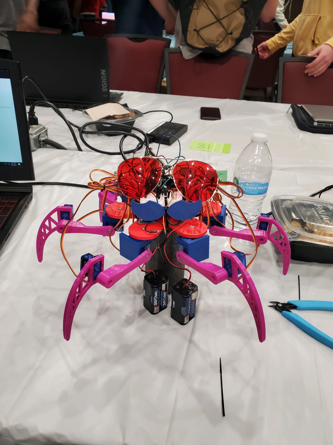
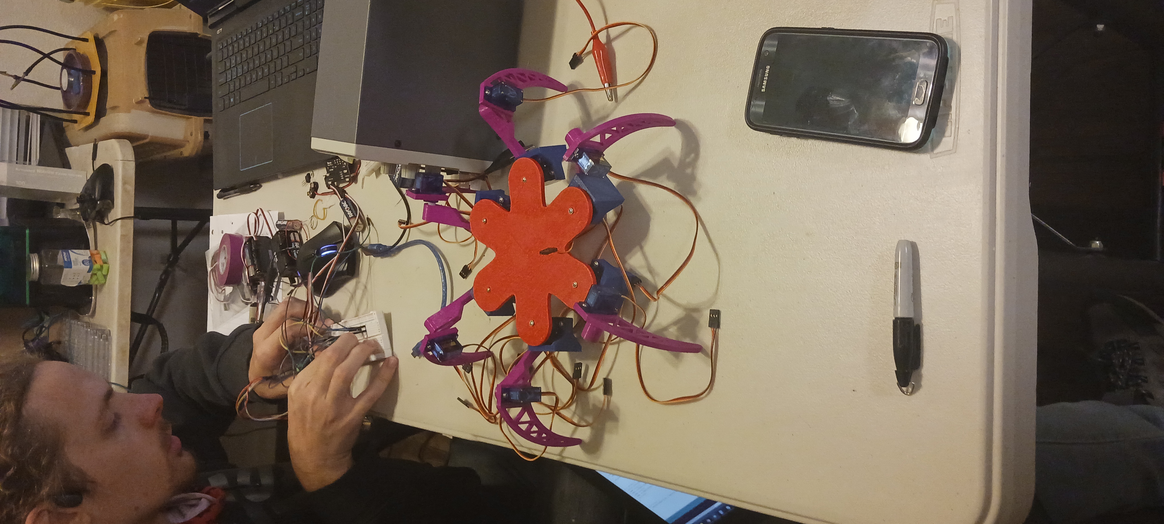
Three friends and I met at the venue this time, and attended the opening ceremony (mostly for the food). We also did our 1hr of brainstorming here, which was routine for two of us. I remembered that I had the hardware to control large amounts of servos, and I also had a lot of servos, so we decided on a mock-up Hexapod. We decided on 18 total DOF, 3 joints per leg, and six legs for stability. We divided into two teams, hardware and software, then divided further into specifics. My role was to draw up the kinematic model for the software, and the logic for movement. My colleague in the software team drew up the i2c communication with the servo controllers, and the other two started CADing. The theme this year was 'Cultural Diversity' and 'Travel', so we were going to make it dance different cultural dances, but we soon realized the limitations of our servos, and the weight of our power supply. We settled on getting it to dance while resting on a support structure.
The body was printed in PETG, the coxae femurs and tibias were printed in PLA (again, in under 24hrs), and the servos were those generic blue 9g servos. The brain was a Nano coded in Arduino, the two PWM servo controllers were hooked up to a 6V power supply each (4 AAAs), and the Nano was powered by a 9V stepped down to 5V using a small power supply we had on hand. I was in charge of the wiring/soldering also. The wiring was done on a breadboard, and with solder in some complex joints.
The script employed a function that allowed the servos' angle to be controlled, and we used a multiplexing technique to get all the servos moving simultaneously. Though it sounds easy, it was the first time any of us had used this hardware, and it took quite a few hours to hit this milestone. Once that was done, we began getting to work making the bot dance. This was also a struggle; we tried to find simulation software that would be able to give us what we needed, but everything was either too large to download, or too primitive to be useful. My friend and I on the software side were in a robot dynamics course, and we actually joked that if the hackathon had been a week later, we could have built the inverse kinematic model ourselves. We settled on preprogramming a dance using trial and error, as time was short at that point.
The robot (which we nicknamed Bitwise Bob) danced, and we won the competition 2nd place out of ~200 people.
VIDEO PENDING
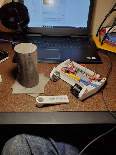
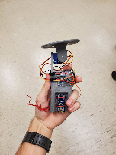
Created with the help of three fellow students, this mug was designed and manufactured in under 24 hours for the Spring 2022 Tamumake competition. Tamumake is a Hackathon hosted by Texas A&M's IEEE student organization.
The idea was sparked by my endless appetite for self improvement, and what better area to improve oneself than water intake. A simple instrumentation system with many parts, and many different materials. The mug is composed of three main sections: the electronics housing, the measurement cistern, and the “cup”. We molded the electronics housing out of fancy thermoplastic, the cistern was printed in 45 minutes on an ender 3 (fastest I’ve ever seen a stepper move), and the “cup” was made of a soup can and some epoxy. The thermoplastic was the kind that becomes malleable when warmed in water, and was used to save time.
The cup had TM1637 4 digit SSDisplay on the front of it, and the arduino uno could be programed with a “goal” for the user in liters. Once set on the table, the limit switch on the bottom of the cup was activated, and after 5 seconds the sonar sensor would measure the cistern level. If water was added, nothing changed but the known water level, and if water was removed, the display showed how much had been taken off the user’s goal. LEDs on the side of the cup also displayed the user’s, and when the user reached their goal, the cup played Take On Me by A-ha on a piezo buzzer. The cistern also closed with a servo to protect the sonar sensor. Though a sonar sensor is more foodsafe than a moisture sensor, we had to use a toxic epoxy due to time constraints.
We won the competition 1st place. Me and my friend each got an Ender-5, and our other teammates chose a different printer as their prize.
My first 24 hour engineering competition; the Fall 2021 HowdyHack Hackathon. This competition is mostly for computer science projects, but my team and I decided that robotics was more fun.
Three colleagues and I created a one-handed ukulele for amputees and people with disabilities. The device was built using an Arduino Mega, laser cut hardboard, spare electronics, a Ukulele, and two large clamps. A combat robot’s left drive motor (from one of my shelved projects (covid)) was used to drive a guitar-pick up and down the strings, limit switches were used to keep the motor from killing the Uke, and a potentiometer-enabled voltage divider was used as a dial to regulate strumming tempo. The dial also featured a pretty circle of LEDs that acted as a speedometer for the device, though the abundance of wires made this feature less appealing than once desired. A rack and pinion gear system was used to flick the pick back and forth, and an irresponsible amount of AAAs were used for the device’s power.
The user need only shape the chords when playing this uke. Unfortunately, we slept for four hours of the hackathon for some reason (a mistake not made in later competitions), and time restraints impeded the potential of the device. It ended up needing to be mounted by clamps instead of straps, and the rack and pinion was re-designed to perform worse than the prototype. It worked, just not as well as the prototype. We did not win this one, but it was the most fun I’d had in a while. Almost no pictures of this thing, on account of the timeframe.
VIDEO PENDING
College Class Projects
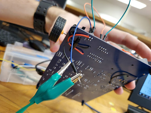
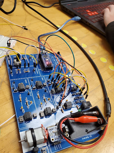
In freshman year of college, I was missing the competitive engineering challenges that high school had given me. So I sought out a bot fighting ring, started building a 3lb drum spinner, and then COVID hit, and the project was stalled. Now, I've revived the combat robot project, and I'm reworking it to be my senior design project. This project is now an ongoing sponsored project of Dr. Rainer Fink, under the supervision of Dr. Porter, Professor Smith, and under the advising of Dr. Kiju Lee.
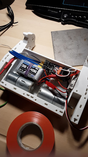
The project is ongoing now, and we are in the research phase with some preliminary design ongoing. The project is centered around increasing the durability of the bot's electronics, a common failure point for competitors in the combat robotics sport. Myself and four other team members are working on building a PCB to house the electronics. This would integrate them all into one board, limiting the number of electrical leads, and the number of failure points thus. The electronics for these bots include a 'weapon' ESC, two drive 'ESCs', a radio receiver/transmitter pair, two drive motors (DC, brushed), one large weapon motor (DC brushless), a battle hardened electrical switch, and a large battery with the necessary specs to power the bot. The ESCs and the radio will be integrated into the aforementioned PCB, with the microcontroller of the large ESC upgraded to an ARM Cortex-M7 'teensy' microcontroller board. Upgrading the board allows us to optimize the ESC's PWM outputs, and further optimize the bot by way of customizable firmware. The wires still remaining on the bot will be soldered to the board using high strength solder (specifics not known yet), and the board's material may even be optimized for shock absorption.
The bot's armor will be waterjet out of 2mm grade 5 titanium plating, the chassis will be 3d printed of TPU and PolyCarbonate, and the weapon will either be 4140 steel, ar500 steel, or an equivalent. The weapon will be a drum spinner; a cylindrical fast spinning drum with sharp teeth along its length. The bot will have two wheels, and the wheel-wells will enable the bot to drive inverted. The bot will have skids on the top and bottom to prevent the weapon from grinding on the floor while driving, even if inverted. The weapon will likely be belt driven using a sonic hub, or friction driven direct. The armor will be at the front of the bot, and the thinnest parts of the chassis will be on the top and bottom. All of these design choices are made with heavy consideration to the known optimal strategies of the sport.
To test the durability of the PCB, and the success of our project, we will be constructing this bot alongside a kit-bot with a successful track record; the fingertech beater-bar kit-bot. This bot will be used to test our own bot by offering a measureable weapon power that we can use to deliver real blows to our bot in simulated competition. Our bot's PCB durability will be judged on its ability to remain functional following direct weapon to armor, weapon to chassis, and weapon to weapon impacts from the fingertech kit-bot, and on its ability to remain functional while delivering the same blows to the kit-bot. It will also endure 12 drop tests onto concrete from 6 feet. I've ommitted much detail for the sake of brevety, but in a nutshell, that is the project.

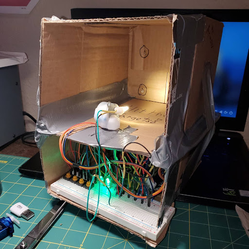
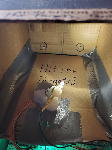
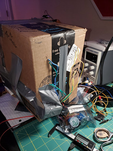
I designed and programmed a turret game for my Intro to Assembly course.
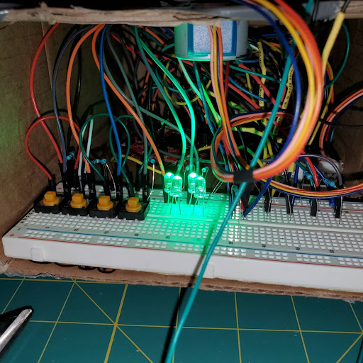
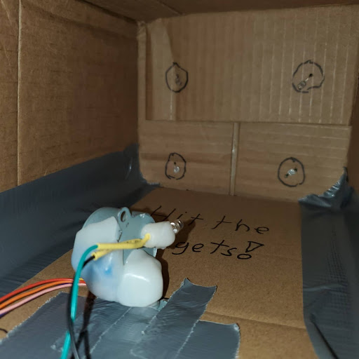
The turret was a white LED that gyrated on two stepper motors, and the goal of the game was to aim the turret’s beam at four photoresistors within a given time frame. Four buttons for up/down left/right controls, and four indicator LEDs that showed which of the photoresistors had yet to be hit with the beam.
The whole project composed of a cardboard box, duct tape, some batteries, an MSP432 microcontroller board, a breadboard for wiring (only time I think I didn’t solder a project), and some thermoplastic for the turret. I built it in around four hours, including the assembly code.
According to the Teaching Assistant, it was one of the coolest projects the professor had seen in that class.
VIDEO PENDING
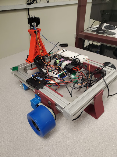
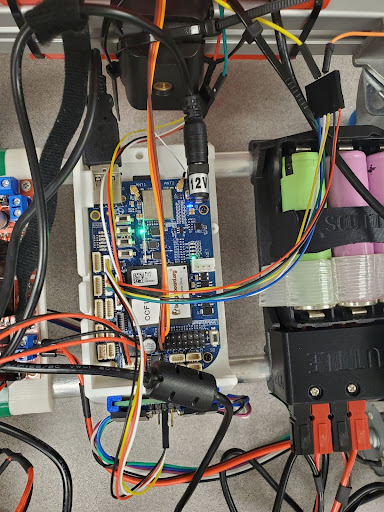
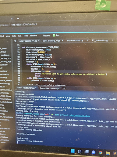
For my Mechatronics 1 course (more like an inverse kinematics & image processing course) my team and I built a robot that detected balloons of a particular hue, and terminated them while also avoiding obstacles. This bot was programmed in Python.
This would have been impressive if the hardware we were using was worth anything, which it wasn’t. The onboard computer (beaglebone) we were provided only had one core. . . and we were using it for image processing. To accommodate for the 3.7 seconds of lag in the video feed, I personally developed a script that did not rely on the typical feedback loop methods of object tracking.
Usually, a bot is coded to move left or right until the object in question is at the center of its vision. Since 3.7 seconds is a long time, the object would never be in the center of this robot’s vision using this system. So using the balloons’ known diameter, the camera’s focal point, the encoders on the wheels, and some funky aspect ratio shenanigans, I managed to get the robot to calculate exactly how much it needed to turn the wheels in order to get the balloon in the center of its screen. This is the same method that is used to calculate the size/distance of celestial bodies.
The rest of the issues we encountered were insignificant in comparison. The robot performed three tasks at once: image processing, obstacle avoidance, and movement. The bot used several HSV masks to isolate the balloons, then pinpointed the balloons’ position on its ‘screen’. The robot would use the aforementioned honing system to align itself with the closest balloon, and would then ram the balloon with a knife. While this was happening, a sonar sensor would detect any obstacles in the way of the bot, and would adamantly avoid obstacles using simple kinematic functions. When a balloon is not detected, the bot slowly spins in a circle until one is.
VIDEO PENDING
I played packman with my biceps for a school project.
My friend/lab-partner for my Electronic Instrumentation Systems course in Spring 2022 devised a device with me to take in EMG (electromyography) signals, and output movements in the computer game Pac-Man. The electronics composed of an Arduino Nano, two band-pass filters (one per arm), and two corresponding EMG filters; both of which were implemented using op-amp circuits. The EMG pads were placed ten millimeters apart on my left and right bicep, and when I flexed, the analog signal going to the arduino would spike.
The software used for this was coded exclusively in LabView (unfortunately). The script created a data file which it then read from to determine whether or not the input could be considered a high signal or a low signal (high being flexed, and low being relaxed). The script then activated keyboard functions using this information to determine which one. Since there were only four possible input combinations, Pac-Man was perfect for this project.
VIDEO PENDING
For my Control Systems project, I built a small self-leveling plate from some spare parts I had lying around my room.
Of course, those spare parts happened to include a 9 axis IMU, some servos, and a microcontroller. Specifically, my team and I used the MPU 6050 9 axis IMU, and I sourced the Arduino Nano and the two servos from the hexapod project mentioned above. In fact, I went ahead and pulled of one of the coxae from the hexapod's legs. The IMU was hooked in I2c serial communication with the Nano, and the servos were powered, grounded, and commanded by the Nano using digital PWM pins. The IMU was also grounded and powered this way. The plan is to have a 'plate' and 'handle' with the 2dof coxa acting as the interface between the two. The IMU in the handle can detect the vector of gravity, and using that we controlled the plate to always orient itself opposite the vector of gravity. Super simple, just the way I like my final projects (my team wouldn't let me do anything more complicated).
The body was printed out of PLA, and the wiring was soldered. . . again, this one wasn't complicated. The script used the 3 axis accelerometer components of the IMU to determine the vector of gravity as a sum of IMU-frame unit vector values. Using this and some inverse tangents I found the angle that the servos needed to be in order to be opposite gravity. The trigonometry was actually quite different than anything I've dealt with before; I had to make 'quadrants' in three dimensional space to account for the four ranges the vector could be in; these corresponded to an 'if' statement each, to allow the proper equation to be used in each quadrant. The device works surprisingly well for how cheap the components are, and for how quickly I built it.
VIDEO PENDING
Extra Curricular Team Projects
Robomasters is an international robotics competition where teams of seven robots engage in simulated combat games. The primary objective is to deplete the other robots' "health", destroy the enemy base, and prevent the enemy from destroying your base. For the gamers reading this, its basically League of Legends but with robots. I'm still on this team, so I won't be sharing too many images or details, as I don't want our oponents getting any intel on our design. The robots are mostly made of aluminum, steel, and durable 3d-printed materials.
In 2023, I was in charge of designing and manufacturing the pitch and parts of the yaw of the autonomous 'Sentry' robot's gimbal turret system. This included most of the "ammo delivery" mechanisms, the pitching mechanism itself, all the electronics enabling computer vision and firing of the ammo system, and all the armor, plates, and housings that encompassed the assembly. The Sentry is a two barrel mobile robot about thigh-height, and in 2023 it had 700 rounds of ammunition. The barrels fire at 27Hz and 30m/s each, and the projectiles are 17mm diameter rubber balls. The fire rate and speed were projects under other teams juristiction in 2023, but the assembly I designed aligned the chambers, ball-paths, and the hopper nested in the "chest" of the yaw assembly, and designed them to fit together with the electronics and other mechanisms of the system. The electronics I organized and wired in the assemblies included four flywheel speed controlers correlating with four 3508 flywheel motors, two competition-specific projectile speed monitors, a realsense depth camera with an Xavier jetson board, a 6020 motor with an internal speed controller, a slipring with a corresponding breakout board, four UV LED drivers to charge the projectiles as they passed through the ballpath, several DJI microcontroller development boards, and another 3508 and speed controller for the hopper's agitator. In 2023, I assembled the yaw and pitch assemblies both in the lab before competition, and during competition for damage repairs.
In 2024 I'm leading the design of the pitch, and coordinating with the leader of the yaw's design. The ammo-delivery system has been moved from the 'chest' of the robot to the back of its 'head', and under my juristiction. The entire pitch assembly only about the size of a flattened football, albeit a little wider, and holds 450 rounds in addition to the rest of the ammo-delivery system. The chambers, agitator housing, and hopper were all redesigned by me to fit this new configuration, and the armor-plate assembly was redesigned to account for the new ammo-delivery system and the new wire-management system that I implemented. The assembly works in such a way that the speed controllers, motors, and camera can all be completely rewired without the need to remove the pitch from the yaw, if need be. Taking off the hopper-agitator housing assembly is simple and allows access to all wires from above, and seperating the two halves of the pitch is also very simple; everything is easy to access and repair while being more functional than its predicessor. The agitator was an especially challenging design, as it was required to be as short as possible in all three dimensions, to house four UV LED drivers, and have two parallel outputs with only one agitator. My design works perfectly even without bearings to smooth the projectiles' path to the chambers. This part coupled with the plates and the hopper are my biggest contributions to the design of this robot thus far. Delegating tasks to my team of engineers has been very helpful. Unlike the previous year, my team-members have been able to take on the less-challenging designs while I spend time perfecting the more sensitive ones such as the ammo-delivery system and wiring layout. The Pitch is currently assembled as of writing this, and the ammo-delivery mechanism is scary efficient; 30m/s alternating fire at 27Hz per barrel with almost no sound and deadly accuracy.
To summarize my experiences in this, I have lead small teams in CAD and assembly processes of large robotic systems, coordinated with other teams and subteams to assure our subassemblies, assemblies, and robots work together, and refined my CAD skills on detailed and complicated parts while also accounting for large amounts of electronic and mechanical components. Soldering, power tools and assembly-labor, wire-layout design, sheet metal and 3d print design, and some CNC design are all physical skills I put to use on these robots. I also used some C programming and digital electronic communication protocols on this project, but those experiences were not as extensive as my electromechanical ones.
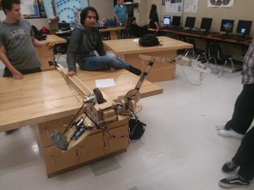
Senior year of high school, I was the Chief Operations Officer of my school’s B.E.S.T. Robotics team. This essentially meant I was in charge of the robot being built for the competition.
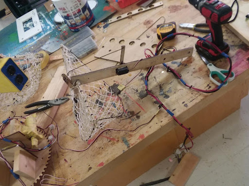
I allocated the skills of a group of five people to various parts of the bot, including the drivetrain and drivetrain latching system (the bot was mounted & driven on a suspended 4x4), the counterweight and its deployment mechanism, and the net. These colleagues of mine constructed solutions under my supervision, while I simultaneously worked on the excavation arm, the bot’s body, the electronics, the code, and the presentation for the bot.
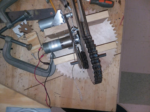
The bot was intended to clean up a simulated ocean in a competition. The bot was suspended on a 4x4 beam, and its arm was to reach out and ‘clean’ the trash out of these nets. The excavator arm we decided on was akin to that of a construction excavator, and was driven at the shoulder by a gear system, with the rest of the joints on string & pulley systems. The bot had to be a certain size before deployment, so the counterweight of the bot was set up so it would kick out once the arm extended.
The bot’s components were either laser cut or made out of plywood using basic woodworking tools. The bot needed to be made out of specific materials that the competition hosts gave us, and so the various components of this bot that seem curious in their material choice are likely a result of these parameters. The counterweight, for example, was made of cans and pennies.
This bot was the third bot I had worked on for this competition, and my time there served as my introduction and inspiration to mechatronics engineering.
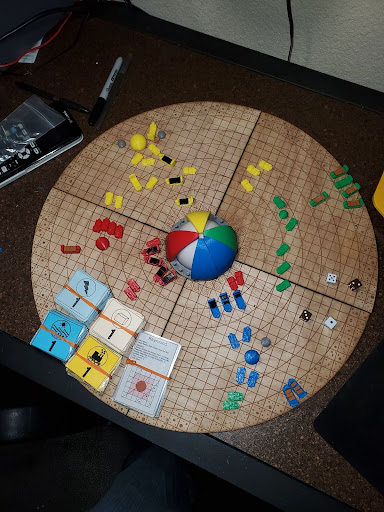
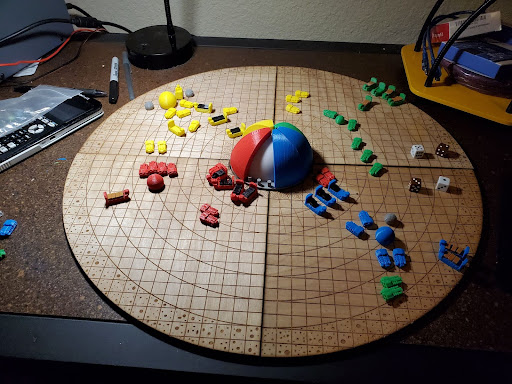
A board game that somes friends and I made in high school. Though, my friends mostly helped with ideas; I did all of the design for the pieces, the board, and the game theory.
In 2019, the Technology Student Association hosted a board game competition in which our team decided to participate. The game is a resource-race that challenges each player to propel their planet toward intra-stellar domination. The players had to balance their material resources and their energy output to achieve control over the system’s star in the form of a dyson sphere. The first player to achieve majority control over the star won the game.
There are many rules, but in essence, the players used their own planet to farm resources and energy, build ships to collect and defend resources and energy, and beat the other planets in the race toward solar dominion. The game had an asteroid belt from which resources could be mined, and an ‘energy zone’ close to the star where energy could be farmed.
The board was composed of laser-cut wood, and a light up electronic star. The pieces were all made up of different colored PLA, and the resource/energy cards were laminated like monopoly money. There were tons of unique planets with different properties. The game would last for hours, and usually ended in a climactic race to the sun.
Extra Curricular Solo Projects
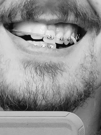
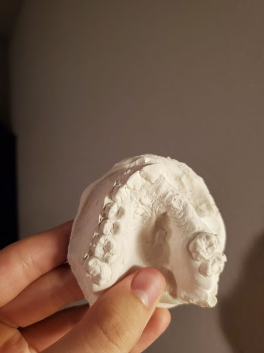
In my freshman year at A&M --right before COVID hit-- I was being careless with my bicycle, and ended up breaking my jaw. I was younger/dumber then.
My injury left me with some open real estate in my mouth, and the prosthetic the orthodontist gave me was uncomfortable. So I asked him if he could get me a plaster cast of my upper mouth. He was able to, and I molded my own prosthetic teeth using the cast. I used this 'seen on TV' thermoplastic that becomes malleable in boiling water, but hardens when cooled. I sculpted the prosthetic on the plaster cast, then heated it up and fit it to my mouth. It is more comfortable than any other oral prosthetic I've worn, and if it ever gets uncomfortable, I can heat it up with a heat-gun and reshape it.
This project is ongoing, however, as there are many things I still want to do. I have plans ranging from oral control of a quadcopter to a simple change of material. The plastic is a thermoplastic, and like most thermoplastics this stuff does not get along with things like spaghetti, curry, or eggs. It stains like tupperware, even when I clean/bleach it. I'm already working on the solution. I'm going to cast a mold of a thermoplastic prosthetic in silicone, then use it to cast a food-safe resin prosthetic. I've got all the materials to do this, I just need to sculpt the prosthetic into a shape I'm more comfortable with before beginning the casting process.
I also have more ambitious plans for this project, as I've previously mentioned. I want to put together some kind of oral electronic device, even if it can't be worn permanently. This could mean replacing one of the 'teeth' with an LED, or installing a small joystick on the 'roof' of the prosthetic to control a quadcopter. There are electrical schematics, but this project has taken a backseat to some of the more pressing projects currently on my plate.
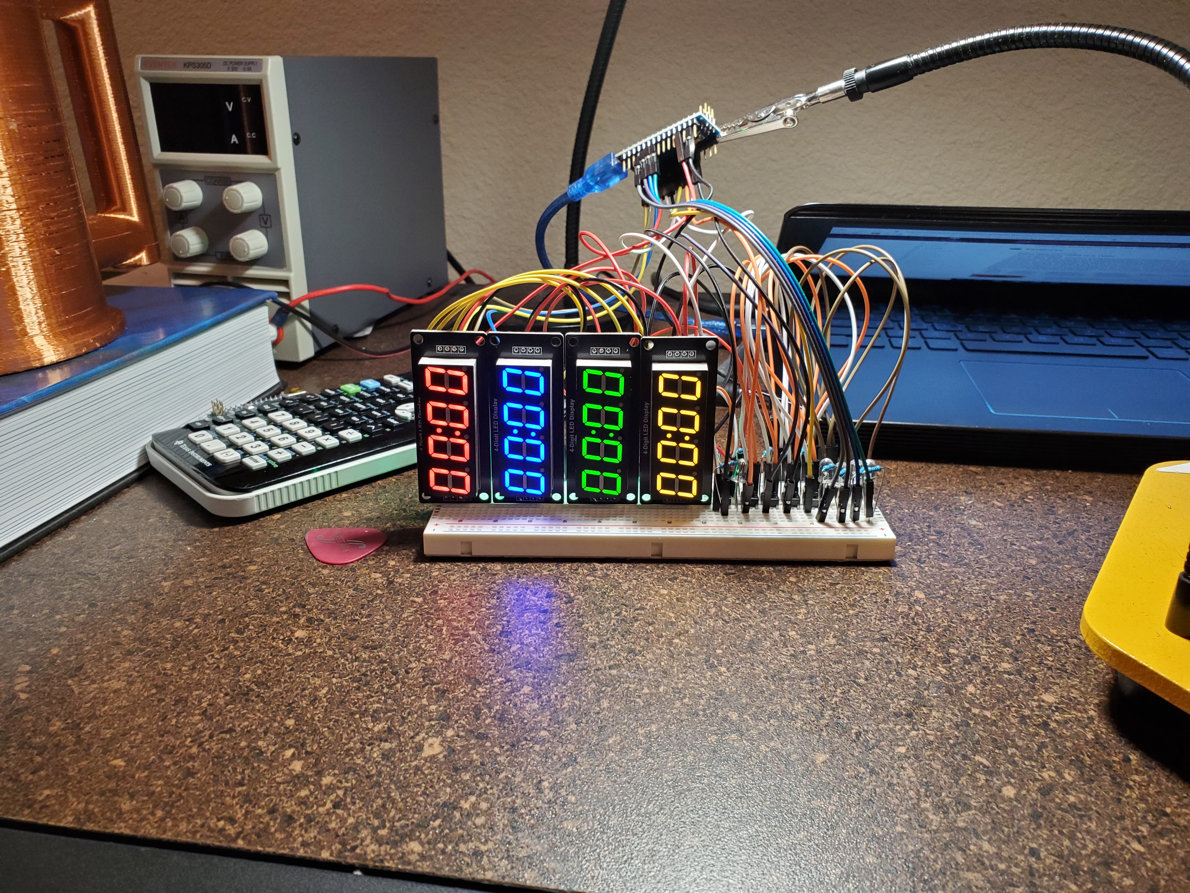
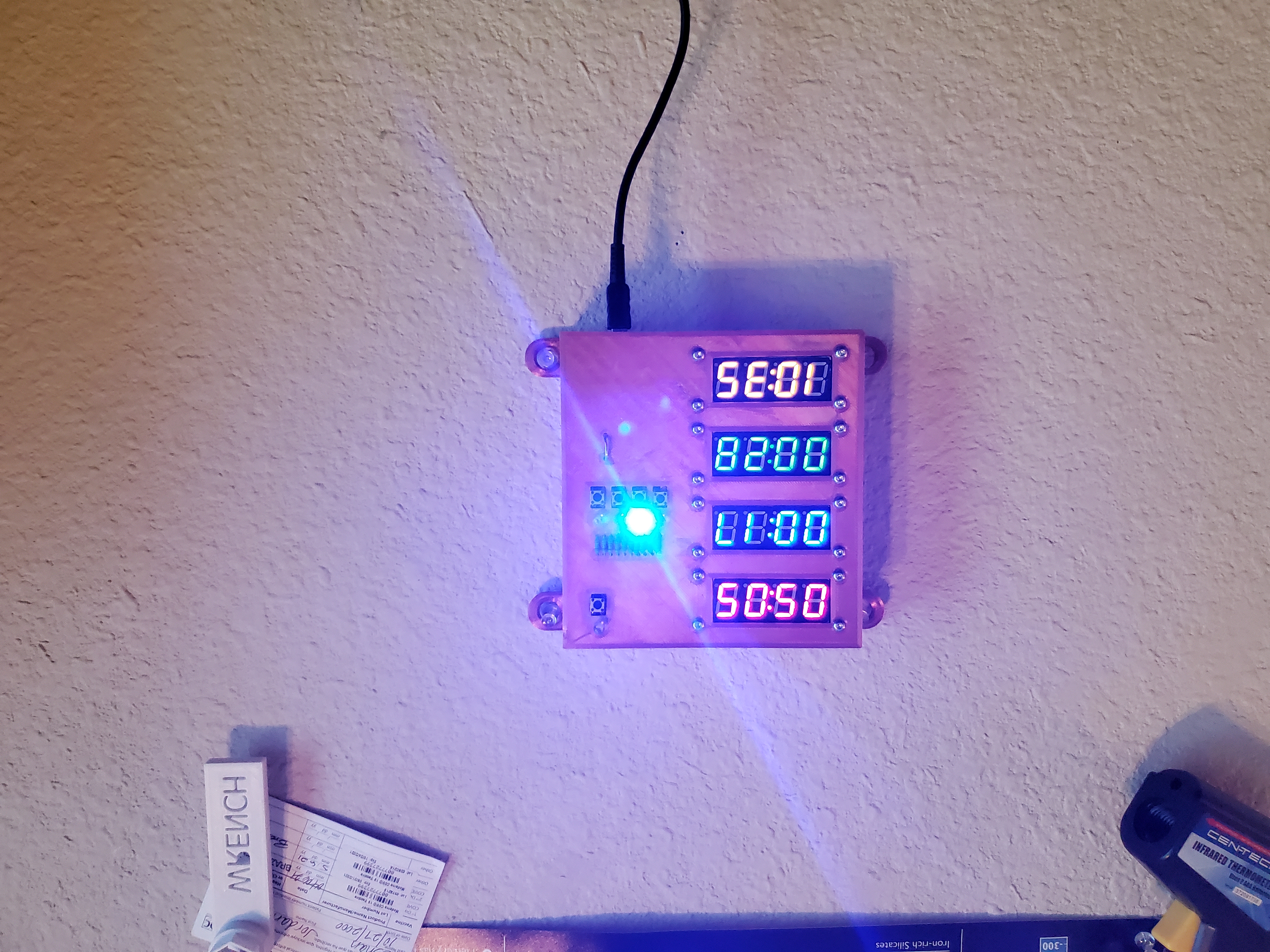
A device composed of three “stopwatches” with corresponding LED blinkers. The device is used to monitor time spent on various tasks throughout my day, and motivate (shame) me to be more productive.
The case is printed out of copper infused PLA on my highly customized Ender 3 (which is now only spare parts). The case was made with many experimental features in place, such as the distasteful resistor display, or the security enhancing square nut housings. The displays slid in really smooth; the tolerances rivaled those of a gasoline engine in some places. The electronics were all soldered and wrapped to hone my skills in wire management and soldering.
I learned how to operate a four digit seven segment display, and integrated one in an instrumentation system. I later switched to TM1637 chip-enabled displays, which were more pin-efficient on my Arduino Nano. I programed the device to run one of four timers, blink a corresponding LED, and to send data to my computer for storage and autonomous plotting/charting. The latter portion of the project was scrapped in the testing phase, when the project was retired after a year. It turns out that shame is not a good motivator.